
A thermal oil boiler must be sized from the process heat demand, operating temperature, circulation flow, startup conditions, and heat losses rather than from the connected equipment nameplate alone. This guide explains how to select the correct capacity, pump flow, expansion system, fuel input, and safety margin for an industrial thermal oil heating system. Genjux can use the same calculation method to help buyers compare boiler proposals and avoid an oversized or undersized system.
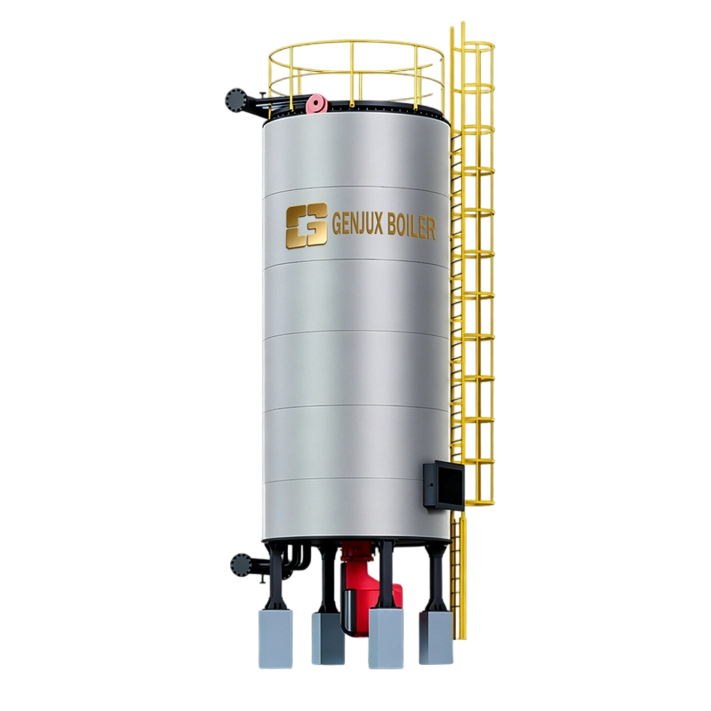
List all equipment that will receive heat from the thermal oil circuit. The boiler must supply the total simultaneous demand of the equipment that can operate at the same time.
Reactors and jacketed vessels
Mixing tanks and storage tanks
Heat exchangers
Dryers, ovens, and curing lines
Evaporators and distillation units
Rollers, calenders, and laminating machines
Hot oil presses and molding machines
Air heaters and process heaters
Tank tracing and heated pipelines
Record the heat duty of each item in kW, kcal/h, Btu/h, or another unit. If the equipment supplier provides only electrical heater power, confirm whether that value represents actual process heat, maximum input power, or installed capacity.
For each process, record the required thermal oil supply temperature and return temperature. The difference between these temperatures is the oil temperature drop, commonly called the delta T.
Required supply temperature, in deg C
Expected return temperature, in deg C
Normal operating temperature
Maximum operating temperature
Startup temperature and heat-up time
Minimum temperature required for product quality
Do not size the system only from the maximum temperature. A process requiring 280 deg C oil may need much more capacity during startup than during steady operation because the equipment, product, piping, and thermal oil all need to be heated.
Determine whether the plant will run continuously or in batches. A continuous process usually has a stable heat load, while a batch process can have a high temporary demand during charging, heating, evaporation, or cleaning.
Hours of operation per day
Number of production shifts
Number of batches per day
Equipment starting at the same time
Required heat-up time for each batch
Seasonal changes in ambient temperature
When several process steps overlap, calculate the load for the highest realistic simultaneous operating condition. Adding every equipment nameplate rating can create an unnecessarily large boiler, while ignoring overlapping loads can cause slow heating and low process temperature.
The sensible heating load is the energy required to raise a material from its starting temperature to its target temperature. Use the following formula when the mass flow is expressed in kg/h:
Process load in kW = mass flow in kg/h x specific heat in kJ/kg K x temperature increase in K / 3600
For a batch process, use the batch mass and required heating time:
Process load in kW = batch mass in kg x specific heat in kJ/kg K x temperature increase in K / heating time in seconds
Example:
Product mass: 1,000 kg
Specific heat: 2.0 kJ/kg K
Starting temperature: 20 deg C
Target temperature: 180 deg C
Heating time: 2 hours, or 7,200 seconds
The sensible heating load is:
1,000 x 2.0 x 160 / 7,200 = 44.4 kW
This value represents only the product heating duty. It does not include vessel heating, heat loss, evaporation, circulation losses, or the boiler efficiency factor.
If the process removes water or another volatile material, calculate the energy needed for vaporization. This load can be much larger than the sensible heating load.
Evaporation load in kW = evaporated mass in kg/h x latent heat in kJ/kg / 3600
If the feed material must also be heated, add both loads:
Sensible heating of the product
Heating of the evaporated liquid to its boiling temperature
Latent heat of vaporization
Heat loss from the vessel and vapor line
Use the actual operating pressure when determining the boiling temperature and latent heat. A process engineer or thermodynamic property table should confirm these values for solvents, oils, water, and other materials.
The vessel, jacket, coil, heat exchanger, piping, valves, and other metal components also require heat. For a batch process, calculate the energy needed to heat each component.
Component heating load in kW = component mass in kg x component specific heat in kJ/kg K x temperature increase in K / heating time in seconds
Add the following items where applicable:
Reactor or tank shell
Agitator and internal parts
Jacket or internal coil
Heat exchanger body
Thermal oil in the system
Uninsulated valves and flanges
Long process piping runs
Heat tracing circuits
Heat loss comes from the boiler casing, process equipment, piping, fittings, expansion tank, and exposed surfaces. Proper insulation reduces this loss, but it should not be assumed to be zero.
A practical preliminary calculation is:
Required boiler output = total process load + equipment load + heat loss
Then apply a reasonable design margin:
Selected boiler output = required boiler output x design margin factor
Typical design margins are often between 10 and 20 percent when the process data is reliable. A higher margin may be justified for uncertain product properties, severe winter conditions, future production growth, or unusually demanding startup requirements. Excessive oversizing can increase fuel consumption, cycling, oil degradation, and purchase cost.
Thermal oil boilers are commonly rated in kW, kcal/h, Btu/h, or boiler horsepower. Convert all process loads to one unit before comparing supplier quotations.
1 kW is approximately 860 kcal/h
1 kW is approximately 3,412 Btu/h
1,000,000 kcal/h is approximately 1,163 kW
1,000,000 Btu/h is approximately 293 kW
For example, if the calculated useful heat demand is 1,000 kW and the design margin is 15 percent, the selected useful boiler output should be approximately 1,150 kW before checking the fuel efficiency and operating conditions.
A boiler supplier may state either useful thermal output or fuel input. These are not the same value.
Fuel input = useful boiler output / thermal efficiency
If the required useful output is 1,150 kW and the expected efficiency is 85 percent:
Fuel input = 1,150 / 0.85 = 1,353 kW
Ask every supplier to state the following items clearly:
Rated useful heat output
Maximum fuel input
Thermal efficiency
Rated oil supply temperature
Rated oil return temperature
Design flow rate
Fuel type and fuel pressure
Operating altitude and ambient design temperature
A single boiler can be suitable for a stable process with a large continuous load. Multiple boilers may be better when the plant has changing loads, separate production lines, or a need for backup capacity.
One boiler usually has a lower initial equipment cost and simpler piping.
Two boilers can improve part-load efficiency and maintenance flexibility.
Modular boilers can allow one unit to operate while another is serviced.
Lead and lag control can match output to changing process demand.
Standby capacity may be necessary for critical production or safety-related heating.
Do not automatically specify 100 percent standby capacity. Compare the cost of lost production, emergency heating, and additional equipment against the cost of a larger or duplicated system.
The thermal oil flow must transfer the required heat from the boiler to the process without exceeding the permitted film temperature. Use the following formula when the required heat load is in kW:
Oil flow in kg/h = heat load in kW x 3600 / specific heat of oil in kJ/kg K x oil delta T in K
For volumetric flow:
Oil flow in m3/h = oil flow in kg/h / oil density in kg/m3
Example:
Heat load: 1,000 kW
Thermal oil specific heat: 2.5 kJ/kg K
Supply temperature: 280 deg C
Return temperature: 250 deg C
Oil delta T: 30 K
Oil density at operating temperature: 720 kg/m3
Oil flow = 1,000 x 3600 / 2.5 x 30 = 48,000 kg/h
Volumetric flow = 48,000 / 720 = 66.7 m3/h
The final pump selection must use the actual thermal oil properties at operating temperature, not water properties and not room-temperature oil data.
Thermal oil boilers require a minimum flow to prevent excessive film temperature and localized overheating. The minimum flow is determined by the boiler design, oil properties, heater surface, and operating temperature.
Confirm the following values with the boiler manufacturer:
Minimum boiler flow
Normal boiler flow
Maximum permitted flow
Permitted pressure drop
Maximum film temperature
Maximum bulk oil temperature
Required flow switch or differential pressure protection
Do not reduce pump flow simply to obtain a larger temperature drop. A low flow rate can create hot spots, oil cracking, carbon deposits, heater damage, and frequent high-temperature trips.
Pump capacity is not determined by boiler size alone. Calculate the pressure drop through the entire circuit at the selected oil flow.
Boiler or heater coil
Supply and return piping
Process jackets and coils
Heat exchangers
Control valves
Strainers and filters
Flexible connectors
Elevation and system layout effects
Use the viscosity and density of the thermal oil at the lowest expected startup temperature and at normal operating temperature. A pump that works at 280 deg C may not deliver the same flow during cold startup when the oil is much more viscous.
Previous: Why Carbon Fiber Propellers Offer Superior Surface Smoothness?
Next: How CNC Machine Cutters Affect Surface Finish: A Practical Machining Guide
Copyright:@2020-2021

Comments Please sign in or sign up to post.
0
0 of 500 characters used