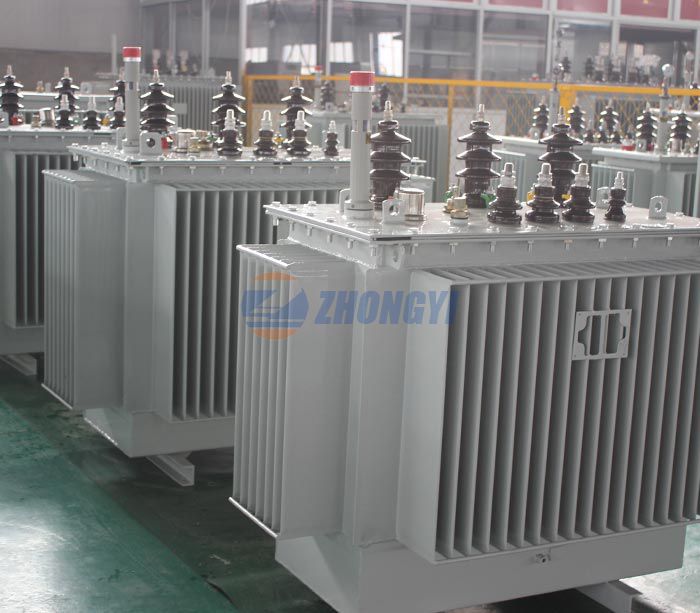
Open circuit and short circuit tests are to determine the parameters of the transformer, such as efficiency, voltage regulation, circuit constants, etc. These tests are conducted without actual load, so the power required for the test is very small. Compared with the full load test, the results of the open circuit and short circuit tests are very accurate.
Open circuit test
The purpose of the open-circuit test is to determine the no-load current and loss of the transformer, thereby determining the no-load parameters of the transformer. The test is carried out on the primary winding of the transformer. Wattmeters, ammeters, and voltages are connected to their primary windings. With the help of AC power, the nominal rated voltage is supplied to their primary windings.
The secondary winding of the transformer remains open, and the voltmeter is connected to the terminals. This voltmeter measures the secondary induced voltage. Since the secondary winding of the transformer is open, no-load current flows through the primary winding.
The no-load current value is very small compared to the full rated current. Because the secondary winding is open, copper losses only occur on the primary winding of the transformer. Wattmeter readings only represent the iron core and iron loss. For all types of loads, the core loss of the transformer is the same.

Short circuit test
The short circuit test is to determine the following parameters of the transformer.
It determines the copper loss that occurs at full load. Copper loss is used to determine the efficiency of the transformer.
The equivalent resistance, impedance, and leakage reactance are obtained by a short circuit test.
Perform a short-circuit test on the secondary or high-voltage winding of the transformer. Wattmeters, voltmeters, ammeters, and other measuring instruments are connected to the high-voltage winding of the transformer. Their primary windings are short-circuited by thick plates or ammeters connected to the terminals.
The low-voltage power supply is connected through the secondary winding, so the full-load current flows from the secondary winding and the primary winding of the transformer. The full-load current is measured by an ammeter connected to the secondary winding.
The above information is provided by the transformer manufacturer.
Copyright:@2020-2021
Comments Please sign in or sign up to post.
0
0 of 500 characters used