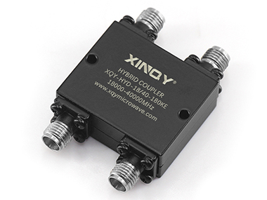
RF hybrid couplers are passive electrical components used in radio frequency (RF) and microwave systems to split or combine signals or to couple portions of the transmitted power in a transmission line. Our RF hybrid coupler provides designers with the bandwidth, high directionality and high power required for the most demanding applications.
RF hybrid couplers have a wide range of applications in various fields such as telecommunications, navigation systems, and military applications. They are used for signal distribution, power dividing, testing, and monitoring.

180 Degree 2.92mm Hybrid Coupler 18-40GHz
There are several types of RF hybrid couplers, including orthogonal (90 degree) hybrid couplers, 180 degree hybrid couplers and coupling line directional couplers.
The 90-degree hybrid coupler has four ports, which are identified as input (IN) port, output port 1 (OUT1), output port 2 (OUT2), and isolation port (ISO).The input port is used to introduce the RF signal into the coupler, while the output port is used to take the RF signal out. The two output port signals have a 90-degree phase difference.For a 3dB 90-degree hybrid coupler, the signal power of the two output ports is equal.No signal power is coupled to the isolation port.
The 180 degree hybrid coupler has four ports, one sum port(∑), one difference port(∆), and two output ports(OUT1,OUT2).Input the signal to the sum port, output in-phase signals with the same amplitude from the two output ports, and the difference port are isolated.Input the signal to the difference port, the two output ports output the signal with the same amplitude and phase difference of 180 degrees, and the sum port are isolated.When two in-phase signals are input to the two output ports, the sum ports combine the two signals.
The coupling line directional coupler has four ports, namely input port(IN), output port(OUT), coupling port(COUPLE) and isolation port(ISO).The input port is used to introduce the RF signal into the coupler, while the output port is used to take the RF signal out. The couple port couple portions of the transmitted power of the input port.No signal power is coupled to the isolation port.
When inputting signals to the output, the input port becomes the output port, the coupling port becomes the isolation port, and the isolation port becomes the coupling port.The four-port directional coupler is a bidirectional directional coupler.Connect the isolation port with the matching load, and the four-port directional coupler becomes a three-port one-way directional coupler.
The working principle of RF hybrid coupler is based on the superposition principle. The input signal is divided into two components, which pass through transmission lines of different electrical lengths respectively, and output two signals with 90-degree or 180-degree phase difference at two output ports. At the same time, the signals returned to the isolation port are mutually cancelled. The phase relationship between input and output signals is maintained by using accurate transmission line length and matching network.
The 90-degree hybrid coupler and 180-degree hybrid coupler are usually designed to provide equal power distribution between the two output ports, with a 3dB loss at the output port. The isolation between the output ports is typically around 20 dB, which means that there is a high degree of isolation between the signals at the output ports. This makes hybrid couplers ideal for applications where the signals at the output ports need to be isolated from each other.
The coupling line directional coupler is usually designed to couple a small part of the power from the input.The typical coupling values are -6dB, -10dB, -20dB, -30dB, etc.
In addition to their signal splitting and combining capabilities, RF hybrid couplers also have some important characteristics, such as frequency response, insertion loss, return loss, and port-to-port isolation. The frequency response of an RF hybrid coupler describes the variation in the insertion loss and return loss as a function of frequency. Insertion loss refers to the loss of power as the signal travels through the coupler, while return loss refers to the amount of energy reflected back to the input port. Port-to-port isolation refers to the amount of isolation between the output ports.
In conclusion, an RF hybrid coupler is a versatile and widely used component in the RF and microwave systems. It is used for signal distribution, power dividing, testing, and monitoring, and its unique design provides equal power split between the output ports with high degree of isolation between the signals at the output ports. With their wide range of applications and their important characteristics, RF hybrid couplers play a crucial role in many fields and are essential components in many modern communication systems.
If you want to know more information RF hybrid couplers, please contact us. We will provide professional answers.
Copyright:@2020-2021
Comments Please sign in or sign up to post.
0
0 of 500 characters used