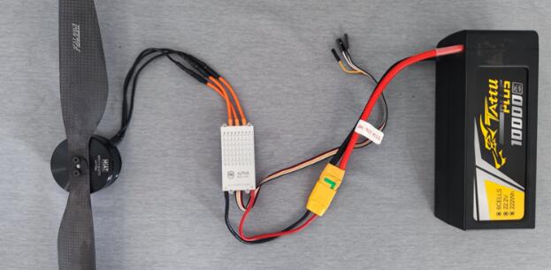
Figure 1.1 Dynamical system connection diagram
The wiring connection mode of the dynamical system on the UAV is shown in the figure above. In order to facilitate the testing of the dynamical system, we install the dynamical system directly on the WF-EDU-02 test platform, and also simulate the installation of the power system according to the wiring connection mode of the power system on the UAV.
(1) Experimental equipment and tools:
WF-EDU-02 test bench: the main body, isolation cage, power line, data line.
Power system: 20A electric adjustment, 3S battery (can be replaced by the internal power supply of the test bench), a set of motor and propeller: motor model is 2312-KV1000 and propeller model is 9450.
Other assembly tools: hexagon socket, bolt, propeller assembly clamp.
Preparation of laboratory equipment and tools
Equipment | Model | Quantity(notes) |
Dynamical system | ||
Moto | 2312 KV1000 | 1 |
| Propeller | 945 | Positive and negative propeller |
| ESC | 20A | 1 |
Battery | 3S 1800mAh | 1 |
Test bench & installation tools | ||
Main body | 1 | |
Protect cage | 1 | |
Power line | 1 | |
Data line | DB9 | 1 |
Motor base | Quick disassembly | 1 |
Hexagon socket bolt | 2.5m | 1 |
Bolt | 4 | |
Propeller disassembly clip | 1 | |
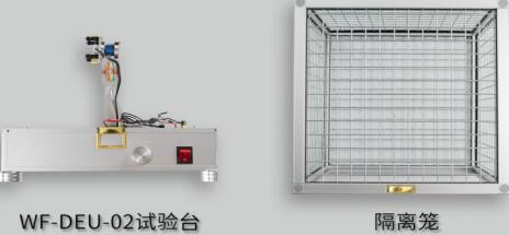
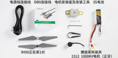
Figure 1.2 Experimental equipment and tools
(2) Assemble the motor and the motor seat, then install and fix it on the WF-EDU-02 test bench, and designate the three-phase line access cable quick connector of the motor.

FIG. 1.3 Motor installation procedure diagram
(3) The electrical conditioning has been installed and fixed on the WF-EDU-02 test bench. The electrical conditioning line is connected with the motor outlet line, and the electrical conditioning PWM signal line is connected with the PWM control signal line.
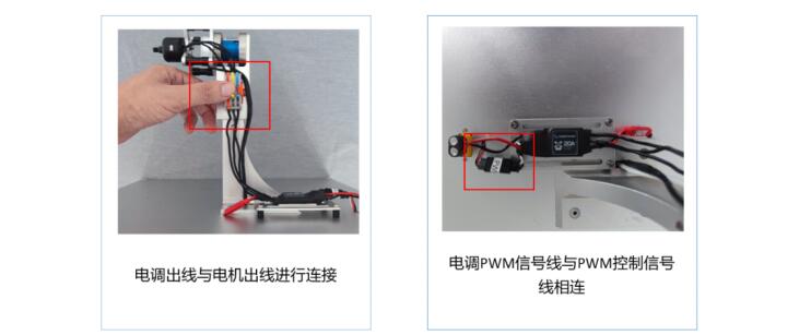
1.4 Schematic diagram of ESC PWM Signal line connection
Note: DuPont plug (3pin) (inset), white for signal wire, black for ground wire, cannot be connected inversely when connected.
(4) Ensure that the motor power switch is disconnected, the power switch is connected to the external power supply, and the battery is connected to the WF-EDU-02 test bench.
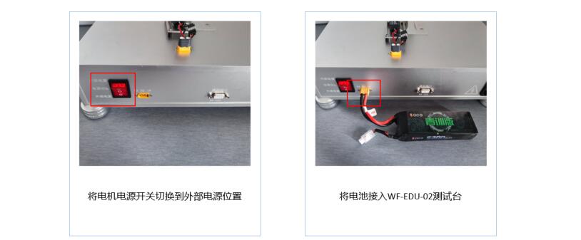
Figure 1.5: Battery wiring diagram
(1) Ensure that the main power switch of the dynamical testing equipment and the power switch of the motor are closed. Insert one end of the power cable into the power hole of the device and the other end into the 220V power supply. Turn on the main power switch of the device. When a beep beep sounds, the device is successfully powered on.
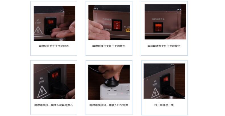
Figure 2.1: Powering on the device
(2) Connect the DB9 end of the data line to the device and the USB end to the computer. Open the MET software, and then the system will automatically connect. The device makes a sound of "didi", indicating that the software is successfully connected.

Figure 2.2: Schematic diagram of software connection
(3) Switch to the internal power supply position, open the motor power switch, at this time, you will hear the "drop --" motor power prompt sound, the motor is successfully powered on. Click the throttle to unlock, the system will appear "didi" prompt sound, the throttle unlocked successfully. Disconnect the motor switch power supply, drag the throttle position to 100%, turn on the motor switch power supply, the motor will issue a "beep, beep" prompt sound, at this time will quickly drag the throttle to 0% position, or press the space bar, at this time, you will hear the "beep --" prompt sound, electric adjustment stroke calibration is completed.
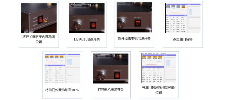
Figure 2.3: Schematic diagram of electrical adjustment stroke calibration
(1) Click the throttle to unlock, and the system will appear a "didi" sound. The throttle is unlocked successfully. Drag the throttle to check the motor steering and record the steering (forward or reverse).

Figure 3.1: Schematic diagram of motor steering test
(2)Disconnect the power supply, replace any two items in the three-phase line of the motor, turn on the power supply, drag the throttle again to check the motor steering, record the steering, through the first and second motor steering experiment, it can be judged that changing any two items in the three-phase line of the motor can change the motor steering.
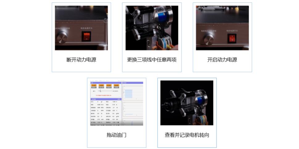
Figure 3.2: Three-phase line steering test diagram of replacement motor
(1) First confirm the propeller steering, motor steering and propeller steering should be consistent, according to the propeller steering, adjust the test motor steering, to ensure that the motor and propeller steering is correct.
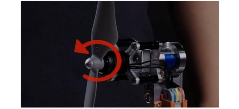
Figure 4.1: Schematic diagram of motor and propeller steering judgment
(2) After ensuring the correct steering of the motor, disconnect the power supply, install the propeller on the motor, use the propeller special disassembly tool (disassembly clamp) to fix the motor, and then tighten the propeller in the direction opposite to the steering to ensure firm installation, and the whole power system simulation installation is completed.

FIG. 4.2: Schematic diagram of propeller installation
When the propeller is disassembled, ensure that the motor power is turned off, use the propeller special disassembly tool (disassembly clamp) to fix the motor, and then disassemble the propeller in the same direction as the steering direction.
This course is divided into two parts: the first part is the explanation of the experimental principle, which explains the basic configuration and assembly principle of the four components of UAV dynamical system, mainly including the propeller and propeller distinction, motor positive and negative rotation distinction, electric adjustment stroke calibration principle and other aspects. The second part is the experimental and practical training, which mainly includes four experimental modules: installation and pre-adjustment of test bench simulation power system, calibration of electric adjustment stroke, motor positive and negative rotation verification test, determination of motor and propeller steering and propeller installation.
Note: After the experiment, please restore the experiment equipment to the state before the experiment, and put the experiment equipment and tools back to the designated position.
Previous: Optical elements, Spherical Lens Manufacturer
Next: Bi-Convex Lenses
Copyright:@2020-2021
Comments Please sign in or sign up to post.
0
0 of 500 characters used